(Unfortunately, I've lost a hard drive, and all my pre-contest pictures have been lost. Most of the pictures here are post battle, so you'll see some dings here and there.)
Overview
AlphaPujo was originally intended to be built as a test bot in order to try out a few concepts. After the original version was built,
I realized that with a few key modifications, AP could be turned into a competitive 12 pound bot.
AlphaPujo 1.0
There were a number of things I wanted to do with AP. From the 1.0 version, I knew I had serious issues with the axles. Since I could not drill a centered hole in the end of the axle to save my life, the wheels would bind during rotation, and this caused further problems with mounting the motors. I definitely had to fix this.
Next, I knew the geometry of my wheels were improper. Turning was difficult, mostly due to the fact that the front and rear wheels were farther apart then the left and right wheels were. I wanted to square up the geometery, which would hopefully make turning more effecient.
I also knew that I'd have to get away from using plexiglass. During the build of DarkMatter, Ted had pointed out a great local plastic supplier (Colorado Plastics), who sold polycarbonate for $2 a pound for scrap. I had pictured scrap as odd shaped pieces 1 foot by 1 foot, but in fact you can get rather large sheets of the stuff as scrap.
Post-Modifications
Frame Modifications
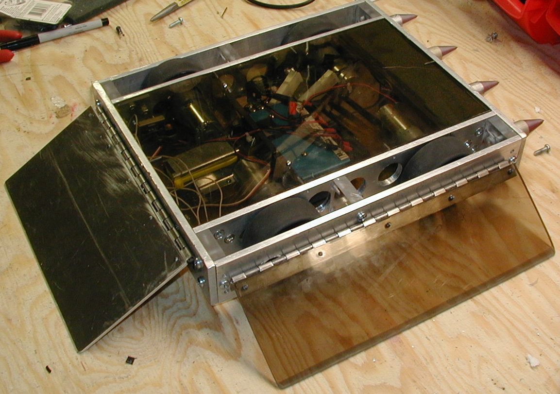
I ended up making a large number of frame modifications. I cut a baseplate from some 1/4 polycarb. Instead of mounting
the base plate below the aluminum frame, I cut it small enough to be flush with the bottom of the frame. I also was not
happy with the L-brackets I had used in the previous version, so I decided to drill and tap 4-40 screws to secure the
base plate. I made the mistake of not using grade 8 screws, so it was easy to strip the heads off of them.
I also got rid of the L-brackets holding the outer wheel covers on. I figured 1/16 of aluminum would not cut it. Instead, I used 1/2 inch polycarb in each corner, and then drilled and tapped into that. I used 10-24 bolts into this. Again, I didn't use grade 8, which I later regretted.

PolyCarb Corners
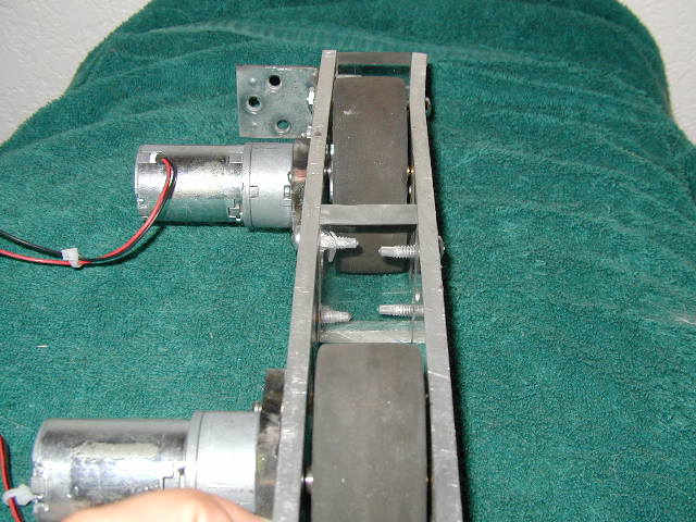
One nice feature of the corner blocks was that it allowed me to remove the wheel assemblies in tact, giving me two wheel pods. The motors, axles and wheels were all ridgidly mounted to these pods. Not only did they look cool, but it made it a lot easier to work on various parts of the bot. I was tempted to figure out how to strap them to my feet for some sweet rollerblades, but never got around to it ;-)
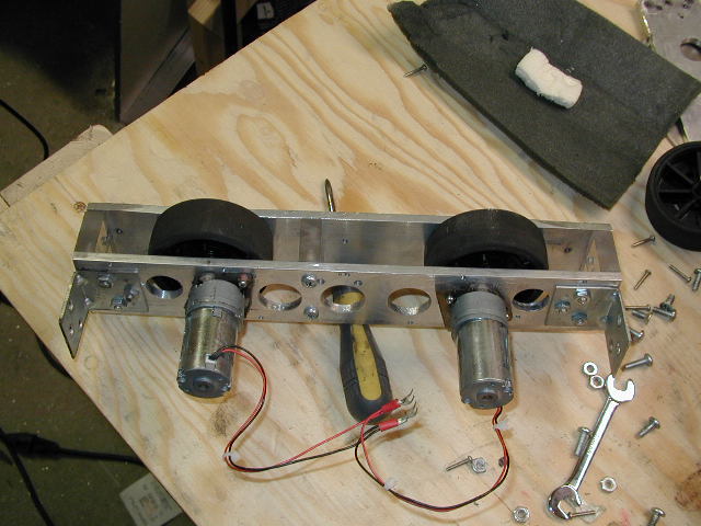
Wheel Pod
I also used some of the same polycarbonate stock as spacers between the two walls of the wheel pods. This would hopefully prevent someone from hitting me from the side, and caving in the aluminium, disabling my bot.
PolyCarb Spacer
Fitting the base plate into the frame brought up an issue that I ran into several times. Since I hadn't been that careful building the frame, a lot of my L-brackets were at slightly different positions in the corners. Because of this, I had to grind a couple of them down in order to get 1/4 clearance on both sides. I quickly realized that my original frame was not very square, and not very consistent. While it seemed OK at the time to "eyeball" the measurements, it really came back to haunt me at various points. Most notably, I only had 3 wheels on the ground at any given time. This cost me traction and power.
I also made a top plate in a similiar fashion. Since it too was recessed into the frame, I was left with 1.5" of room inside the frame for the good stuff.
Motor/Wheel Mounting
I decided to move both the front and back wheels toward the center of the bot, in order to improve turning perfomance.
In version 1.0, I had used ball bearings to support the axle. They had a fairly large diameter, and a bit of weight to
them, so I decided to try my hand at using bronze sleeve bearings. They weighed a lot less, had a diameter just 1/16
larger then the axle, and are relatively inexpensive. This also allowed me to avoid an issue raised by the fact that I
had drilled a bunch of lightening holes in the frame, just for fun. The damn lightening holes came back to haunt me a
lot on various mounting options. I guess the lesson is to drill your lightening holes last (although, when I drilled them,
I truly thought I was done with AP...)
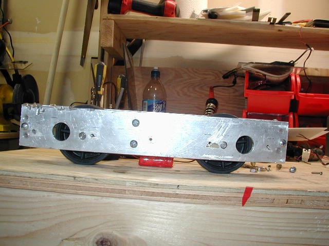
Wheel placement changes
I also decided to bias the wheels toward the bottom of the frame. One thing that Ted and I learned at TI was that having a small amount of ground clearance was quite dangerous. While it may seem attractive in order to prevent other bots from getting under you, it actually can cause you to become high centered quite easily. I had planned on using hinged skirts so I gave myself approximately 1/2" of ground clearance on the bottom of the bot. If I got flipped over, I still had about 1/8" ground clearance. I basically was hedging my bets on not getting flipped.
I was not happy with my original solution of using L-brackets for motor mounts. I decided instead to try using 1/4" polycarb to bolt to the motor, then bolt the polycarb to the frame. In retrospect, I could have just bolted the motors directly to the frame, but at the time I wasn't too confident I could blindly drill the hole pattern correctly into the frame.
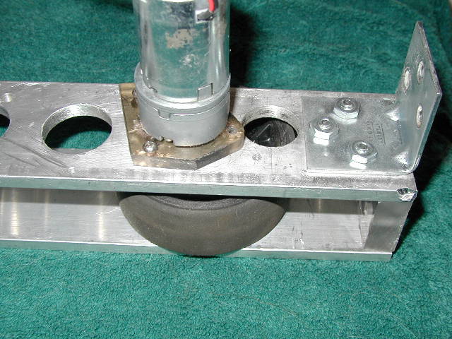
PolyCarb Motor Mounts
I had recently picked up a 6" and 12" set of calipers off of e-bay. These made drilling the hole pattern a lot easier. In fact, I don't know how I got along without them before.
One big mistake I made when making the motor mounts was due to not thinking ahead enough. I ended up making each motor mount unique, which was a drag in itself, but it wasn't until I made the last motor mount that I realized it could also act as a base/top plate support as well. Consistancy would have really helped out here, along with a design commited to paper, rather then just making it up as I went along.
Ted had been kind enough to turn a few axles for me on the lathe he had access to. This took care of my wobbling axle issue.
I ended up attaching my wheels to the axles the same way I had before, by just using a nail as a pin. I was a bit nervous about this, since I had sheared a nail previously during test driving. The plan was to replace it with something stronger later on. This never happened.
I also attached the axle to the output shaft of the motor in a similiar fashion, although I used a cotter pin instead, which seemed a lot sturdier then a nail.
Electronics
I made a few slight upgrades in the electronic department. I kept the same 4 small barber-coleman motors. I also
continued to use my Vantec RDFR23, and 8UAPS receiver. However, I upgraded my drive batteries to some 1.2 AH nicads
I got off of e-bay. This allowed me to run at 24 volts with 20 batteries for 1.2 AH, instead of previous batteries
I had, which required 40 cells to give me the same number of volts and amp hours. This gave me a lot more room to
play with internally.
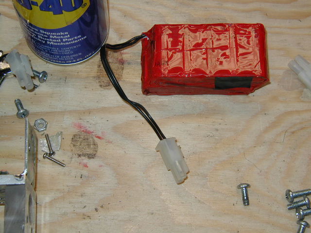
$2 Battery Pack
I also bought a battery eliminator circuit from Dan at Team Delta. I really liked this solution, due to the fact that I had to worry about one less battery source and one less switch. Pretty slick. The thing weighs next to nothing too, and is easy to install. (Starting to sound like an ad...)
Battery Eliminator & Receiver
I mounted a simple switch to the side of the frame that was protected by the wheel guard. It was probably a pretty wimpy switch, but in theory, I'd be pulling very little current when the switch would be flipped.
For wiring, I soldered all my connections, and used the proper type of connectors. I used the spade type for going into the Vantec, and "the loopy kind" for bolting to the terminal strip. I gave up on the 12 to 24 volt switch, and just hard coded the terminal strip to be in 24 volt mode. I put a few cheapo quick disconnect connectors on the batteries and terminal strip, so it was easy to pull the batteries out and charge them. I made 4 complete sets of battery packs, so I had no fear of getting to a point where I had no spare batteries. I gave up on the idea of charging the batteries while they were in the bot, mostly due to the fact that I didn't have a 24 volt charger. It would be a nice feature to add in the future though.
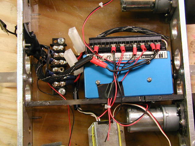
Wiring
I also taped off any exposed electrical connections, as well as the open face of the Vantec. There is an excellent thread on the BattleBots forum entitled "How Not To Fry Your Vantec" that I tried to follow as closely as possible.
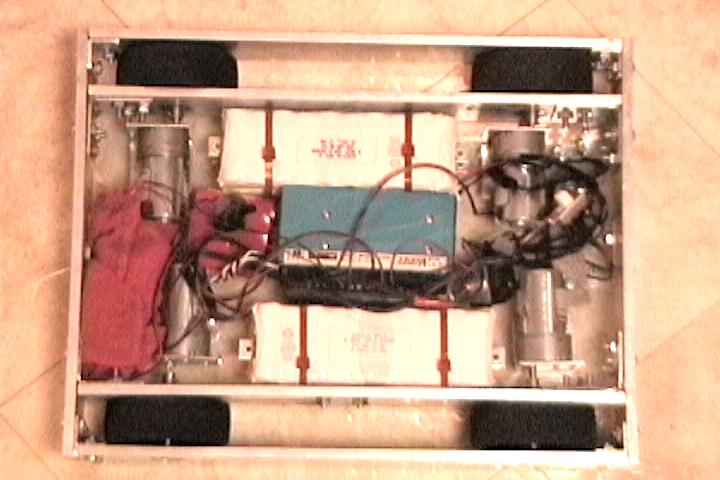
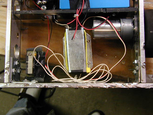
I spent a good amount of time securing the electronics to the frame. I used two internal walls to hold the Vantec and the batteries in there respective places. I bolted the battery eliminator directly to the base plate. I fashioned a receiver box out of very thin steel, and attached it to the base plate. I made sure it was very accessible, because it looked like I'd need to share the receiver between bots.
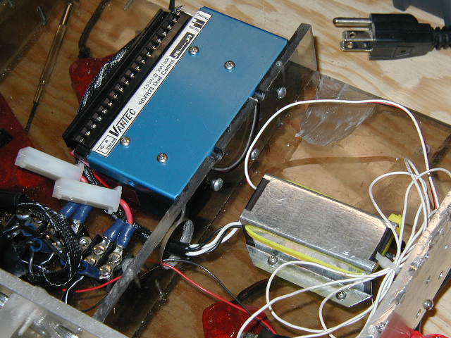
Vantec Mounting
I paid special attention to the battery compartment. The batteries represented the single heaviest component in the bot, other then the frame itself. Thus I used more bolts here then in other areas.
I had a Dean's antenna from Team Delta, but unfortnately did not have time to install it. I ended up having minimal RC issues that could have probably been avoided if I had used the Dean's antenna.
Weapons
I was out of weight to add any really interesting weapons. I weighed AP at this point and came in at roughly 10 pounds.
I added a 1/8" aluminum hinged wedge to the front. I ordered some piano hinge from McMaster, and this worked out great.
I also added side skirts, using 1/4" polycarb. I gave up on trying to fashion cool BioHazard styl slanted edges to the hinge, mostly due to lack of time and lack of polycarb/aluminium. I hand filed the ground edges so that they were nice and flush to the ground. I curved the corners due to some of Jason Bardis's advice I saw online.

Side Skirt
I also fashioned some stoppers out of polycarb to prevent the skirts from folding up and lifting all the wheels off of the ground. The trick here seemed to leave enough play in the skirts (and front wedge) so that they were always resting on the ground, but only give them the ability to travel 1/2" lower.
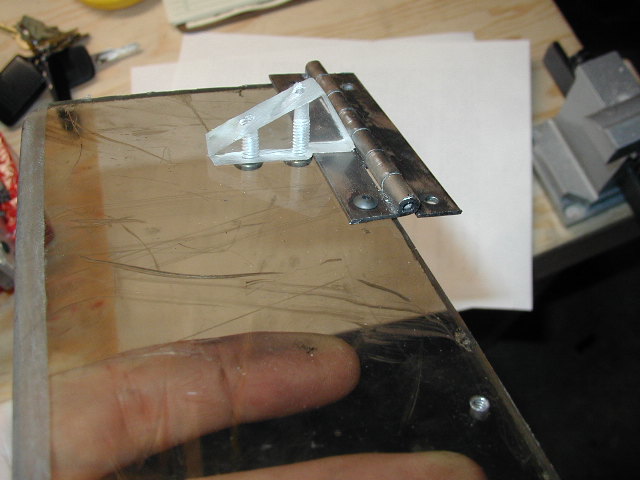
Skirt Stopper
On the back of the bot I added four large aluminium spikes that Ted had given me. I added these relatively late in the game, and they were a little too long for my tastes, but I didn't have time to shorten them. They were more cosmetic then effective.
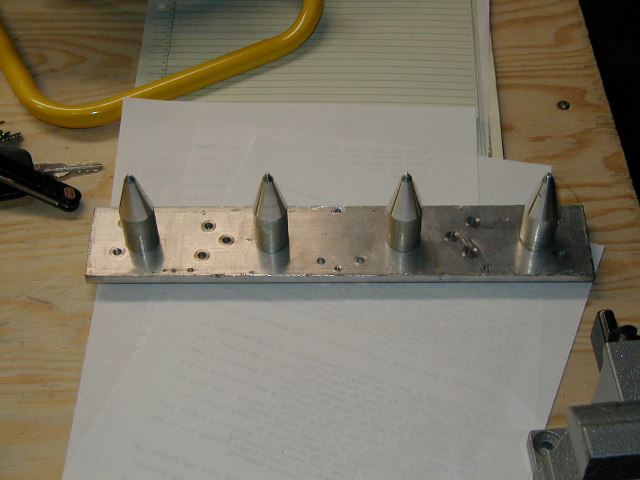
Spikes
Miscellaneous Notes
I have yet to have anyone confirm this, but I seemed to have problems using LocTite on polycarb. Nearly
every hole I used it in ended up fracturing just by tighting the screw. This may have been just a coincidence, but it was
enough to keep me from using LocTite on polycarb.
On the topic of LocTiting, I found myself LocTiting parts of the bot many times, just because I'd think I was done, and then realize I had to dissassemble parts to make a change.
Similiarly, I ended up using the risky practice of drilling holes into the frame, while the electronics were on board. If I had more time, I would have avoided this, in order to prevent from stray flakes from entering sensitive areas.
Previous incarnations of AP had a symmetric layout. I decided to go against this for a number of reasons. Since I had a wedge up front, and spikes in the rear, I placed all the batteries near the rear. Since the front wheels had moved back about an inch, there was a good amount of overhang on the bot. I was afraid that someone driving up the front of the wedge would cause the bot to lift it's rear wheels off the ground. I hoped by placing most of the weight near the rear this could be avoided. Also, since the spikes were in the rear, I hoped that having a lot of weight near them would make them more effective.
I broke two taps while tapping 4-40 screws. In retrospect, I probably should have used more 6-32s instead. Of course, the taps broke off in such a fashion that I couldn't remove them, so they now enjoy riding around as part of AP's frame.
Conclusions
After all the heavy modifications I made, I was happy with the results. I now had a bot that I felt a lot more confident
about taking into battle. The thing was rock solid, handled well, and most importantly, it looked cool! The only
aspect that I wasn't completely happy with was my motor selection. Even at 24 volts the bot moved pretty slowly.
The perceived speed of a bot in a 5 foot area is a lot different the perceived speed in a large
arena. The overhanging frame on the front and the rear of the bot was also a bit of a concern to me.
BotBash PostMortem
(Battle Log Here)
Alpha ended up taking third place in the 12 pound division at BotBash. This was better then I expected, and I suspect a lot of that has to do with luck. The main problem I had was with my motors. They were very slow compared to the competition. I didn't get to see all the bots fight, but I'm willing to bet I had the slowest bot there. Luckily the sturdy frame helped me survive many hard hits, and I never had anything come loose, or structural failure of any kind. The arena floors were very slippery, and thanks to the surplus wheels I had, I had better tranction then most. I hope to continue to use these wheels in the future.
I feel that one reason I did as well as I did, was my hinged wedge and skirts. In fact, the three bots that had hinged wedges filled 1st, 2nd, and 3rd places. I expect to see more hinged wedges at the next bash.
Not only was my bot somewhat slow, but 3 of the 4 motors died by the end of the competition. This wasn't due to them getting smoked, but due to gear box failure. Since I had over-volted them 2X their spec, the gear boxes just weren't up to the job. Faster more reliable motors would have made a world of difference. On the brigher side of things, I liked having the highly redundant drive train. It probably made the difference between winning and loosing for several fights.
My wheel overhang problem came into play, but just a little. HyperActive in particular got on top of me (all 24 pounds) and caused AP to lift a set of wheels off the ground many times. This really didn't seem to cause any real damage. I still plan on moving the wheels closer to the front and rear of the bot.
I did have some pretty good radio interference issues. Instead of installing the Dean's antenna, I just looped the antenna up, and ziptied it. In fairly random spots of the arena, AP would loose contact, and continue to move until the failsafe kicked in. This lead to some exciting moments, again particularly against HyperActive.
My sleeve bearings did slip out of the frame on occasion, but didn't seem to adversly effect things (hmmm, maybe they contributed to stripping the gear boxes??) My batteries worked fine, as did all the mounting plates.
I realized that I had made a wiring mistake. With the batteries plugged in, and the power switch off, my battery eliminator was still powered! This caused a slow drain on my batterries, and explains why they were dead after arriving in Phoenix. Oops!
What's Next?
Now the search starts for better motors! I did buy some faster motors that were roughly the same size as the originals. When I overvolted them to 24 volts, they had roughly a 1000
RPM, which gave me a running speed of about 8mph. What I gained in speed, I lost in torque, and poor AP couldn't turn to save his life. It was fun blasting around in straight
lines though, until one of the gearboxes stripped.
After that experiment, I got serious. I bought a digital scale so that I could weigh existing components. After looking at all the motors available, I found some that should be decent replacements for the Barber Coleman motors, and not break my weight budget.
I also took the time to model the newly upgraded AP in AutoCad. Rather then having a rough sketch of the layout like I did last time, I now have a very detailed diagram of exactly where every component will go, and a good estimate of how much AP will weigh.
Look for a new build log soon!