
Ted Zeiger
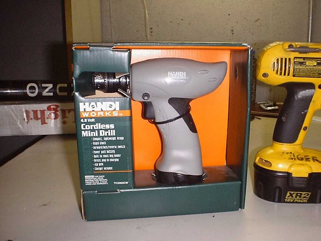
The beginnings of IO came out of searching for a new drill motor for Neutrino. While cruising the tool aisle of my local Walmart I came across a little drill that showed much promise. The Handi-Works brand drill only cost $16, and they had many in stock. This new drill ran at a meager 4.8V, but had a top speed of 450 rpm. Upon further inspection, the documentation revealed a stall torque of 15in-lb. I quickly grabbed 4 drills and headed home for testing.
Here is what the Handi's look like before you tear them open. In the picture below you can see my 18V dewalt for size comparison.
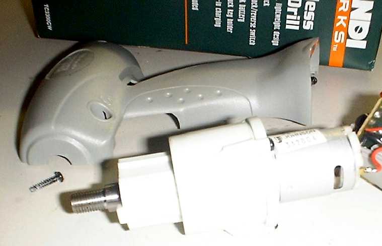
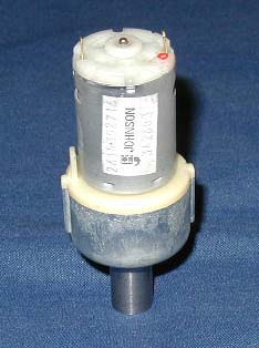
After opening a drill up I was pleased at what I saw. The gearbox assembly was quite sturdy. In fact the gearbox is nearly identical to those found on larger generic drills, even up to 18V. But unlike the larger drills, these had no clutch that would need to be disabled. The motor was rather small, the same size as those found in the Black and Decker screwdrivers. However, because I was planning on using 4 motors, the small motors seemed appropriate.
After I removed the drill chuck and pulled the motors out of the housing, I was able to take some measurements. The motor and gearbox together weight 9.5 ounces. The output of the gearbox is a 3/8 fine thread (3/8-24). The motor is about 1 1/2" long and 1 1/8" in diameter. The gearbox is about 2 1/4" long and 1 7/8" in diameter at its widest point.
For wheels, I chose some 3" diameter by 7/8" wide Colson Performas that I had sitting on my shelf of robot parts. I had picked these up at my local hardware store a while back thinking they would be perfect for 12 pound robots. (They can be bought from McMaster-Carr as well.)
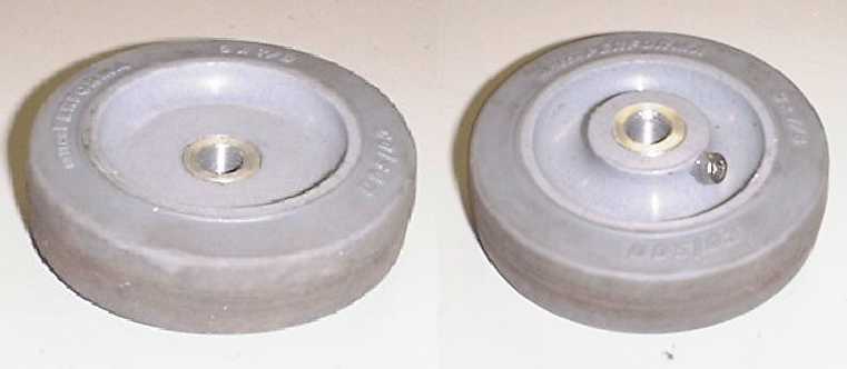
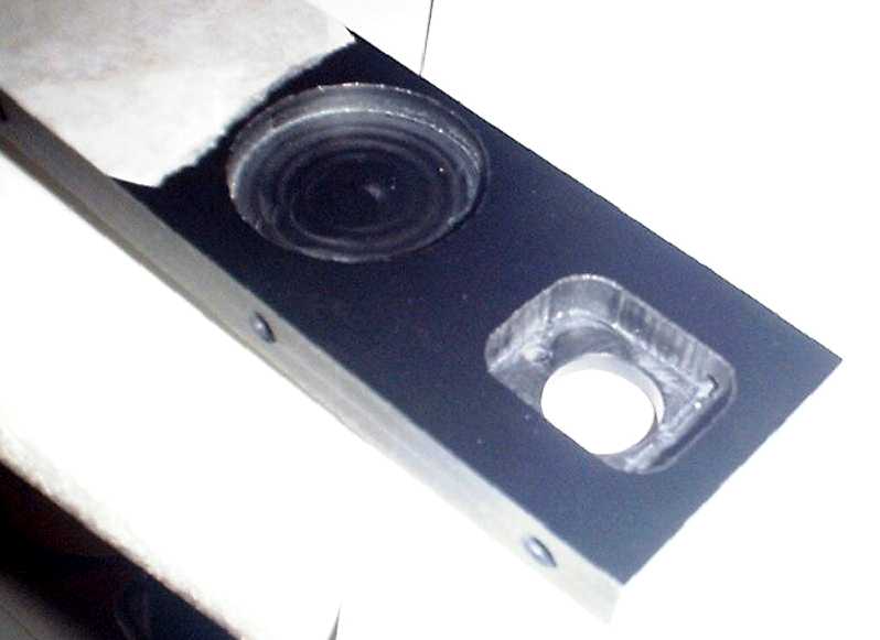
To mount the wheels to the drill motors I made a very simple hub. With the plastic bushing removed from the Colsons, the bore is 0.605" at its smallest point. (Note that the bores have a bit of taper.) Using a lathe I turned down a piece of aluminum round stock to around 0.607". This would provide a tight press fit, and allows for the taper in the bore. Then, using a size Q drill, I bored a hole though the center of the hub. The Q is the proper size to drill for a 3/8-24 tap. After pressing the hub into the wheel I pinned it using a machine screw to be sure that it would stay but. I would bet that the press fit would have been enough for a 12 pound robot, but better safe that sorry. After securing the hub to the wheel I tapped out the bore of the hub. To attach the wheels all I needed to do was thread them onto the output of the gearbox and install the left handed screw used to hold the drill chuck.
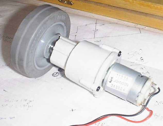
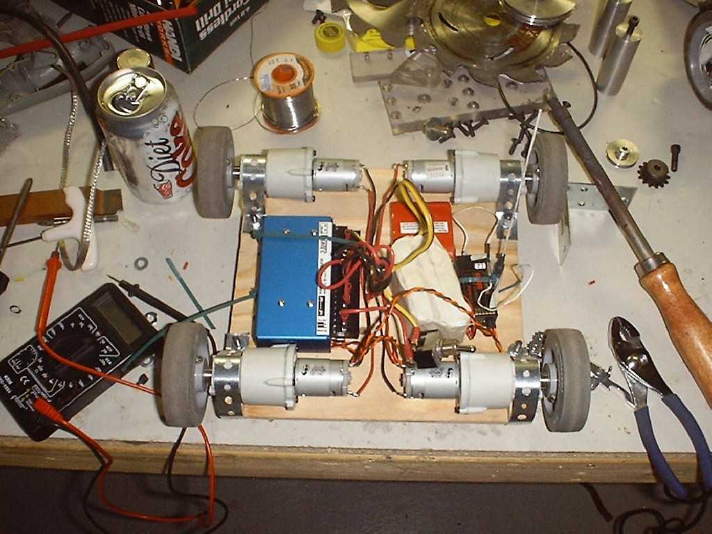
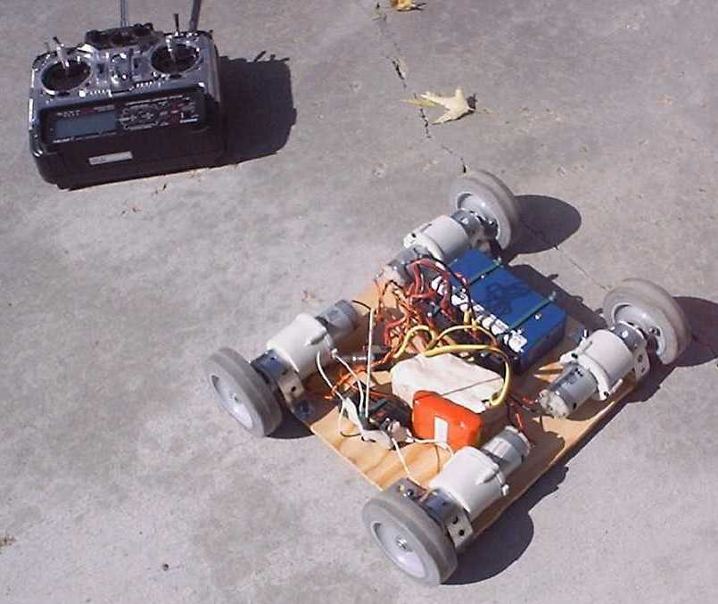
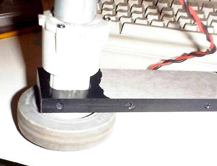
Once I had 4 wheels and hubs ready, and 4 motors stripped out of the drills, it was time to make a test platform. The base was some 1/4" plywood, and plumber's strapping held on the motors. Running the motors at 7.2V the test robot was quick but still very controllable.
The test robot showed that the Vantec speed controller was not a good choice for such a small robot. I had won a Vantec RDFR23 at BotBash 2001, but later decided to go with hobby speed controllers. These would be more than adequate for the small motors and take up less space. Tekin Rebels had worked for me in the past, so I used them again. (I later sold the Vantec and bought a pair of Victors.)
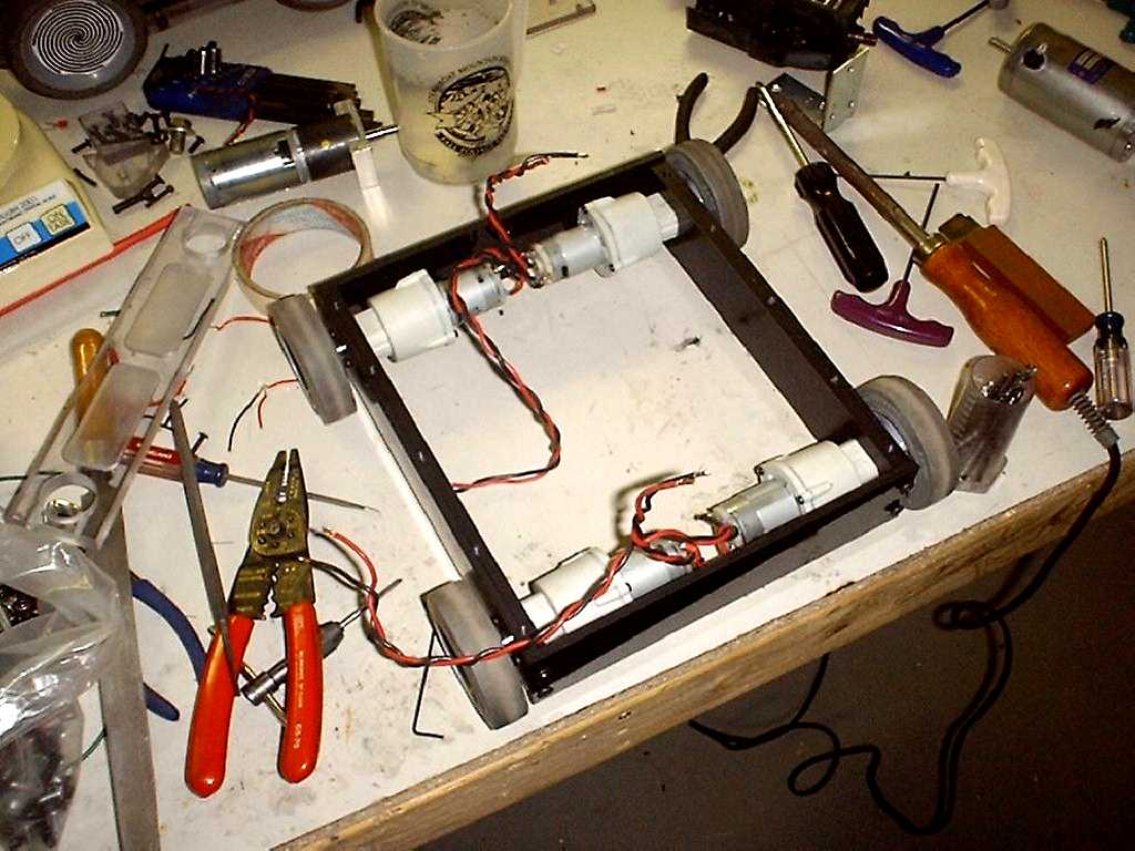
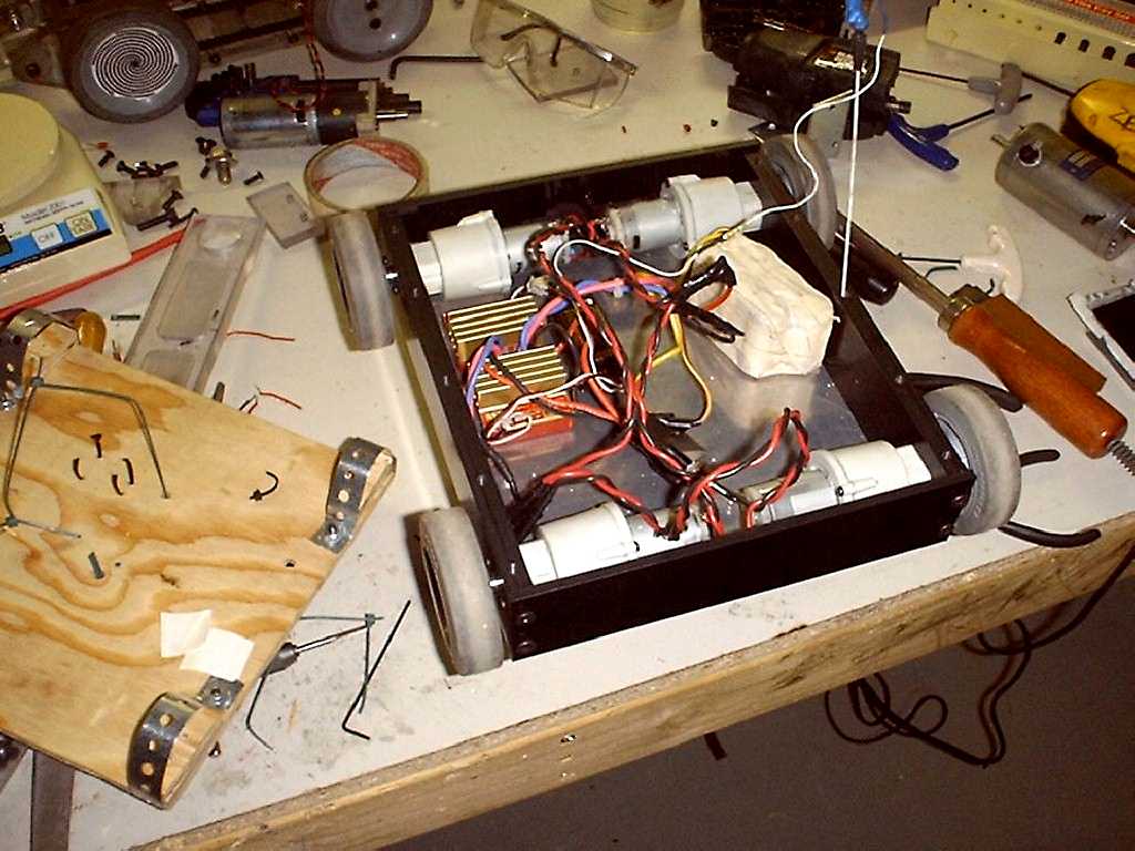
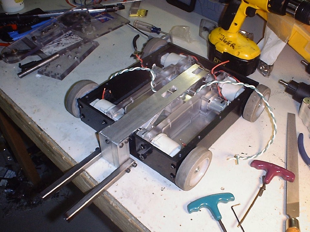
To mount the motors to the frame I used a mill to cut a pocket the same size as the nose on the gearbox. Then I tapped the two small holes on the front of the motor with a 6-32 tap. This would secure the motors to the frame rail. With 4 motors installed in a simple frame, it was time to make more refined test robot. This allowed me to double check that the Tekin ESC's would be sufficent and that the wheel spacing worked well. I lengthened the wheelbase over the original test platform to make sure that there would be room for a weapon.
For a weapon, I decided to try a simple lifter arm. Originally I planned on using a gearhead motor I picked up from All Electronics. This motor had plenty of torque, but was rather large and heavy. Furthermore, it would need at least 12V to run fast enough. Because I was only planning to run the drive motors at 7.2V, this would mean that a dedicated battery pack would be required for the lifter motor.
After some brainstorming, I realized that if two Skil Twist brand screwdrivers would do the trick. At there native 3.6V, they have a max torque of 40in-lb. Thus running two of them at 7.2V would yield 160in-lb.
Our first BattleBot, DarkMatter, had a simple pivoting lifter. After seeing the effectiveness of BioHazard's lifter, I decided to try something similar. Designing the geometery of the 4-bar lifting arm was not trivial. I had to employ my old Mechanical Engineering handbooks to calculate torque needed to lift 12 pounds. The two Skil screwdrivers drive the rocker, while the lifting forks are connected to the coupler.
One advantage of a 4-bar lifter is that the fork rises much more quickly, and the linkages act as a gear reduction, compared to a normal pivot lifter like we used in DarkMatter.
In order to control the lifter, I used a Team Delta RCE220 which is a basic RC controllable H-Bridge. In order to avoid burning out the screwdriver motors, I installed micro-switches to signal the RCE220 to stop at the end of travel.
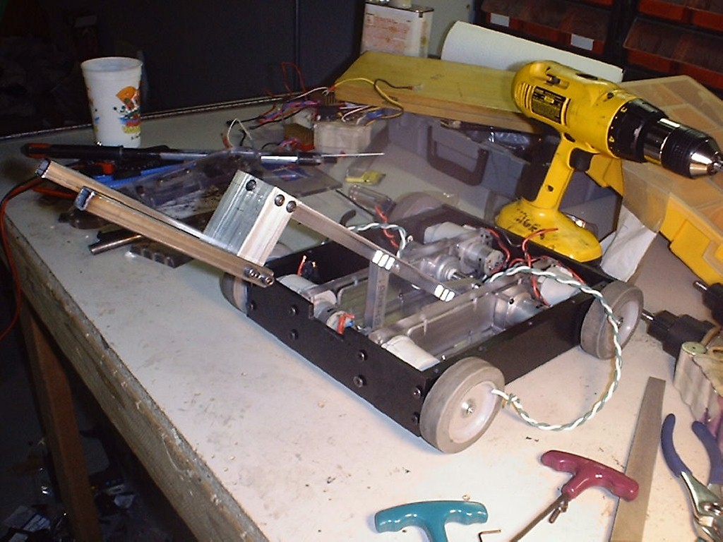
I machined the lifter components out of 6061-T6 aluminum. The forks were .5" box steel with 1/16" walls. I used 1/4" diameter shoulder bolts at the pivot points.
After wiring things up, I was surprised by the speed of the lifter. I worried that at that speed I would not have enough torque available to lift a 12 pound bot. But as it turned out, the 4-bar linkage's mechanical advantage proved to have the power needed to lift over 12 pounds. Further calculations predicted a maximum lifting capacity of 15 pounds. I figured this would work for the upcoming NERC event.
The last feature I wanted to add was two small wedges to the front of the bot. I wanted to make sure that I had an alternative attack, in case my lifter failed. Also the wedges helped get the lifter under the opponent. Lastly, the wedges would help defend against some of those 24 pound walking spinners. The wedges were attached to the front polycarb via some piano hinge from McMaster Carr.
Packing everything in the frame was a bit tight. Routing the wiring properly took a lot longer then expected. I had to drill a few holes in internal frame members to route some wires. This made servicing various components nearly impossible without disassembly. All designs require some compromise, I sacrificed servicability for frame strength.

That about wrapped up the 1.0 version of IO. I took IO to the NERC sponsored HSRC02 event. To my surprise, he ended up taking first place. As in any competition, luck played a big factor. There were a lot of heavy hitting kinetic weaponed bots there that IO avoided in the brackets.
IO performed well, although G-Minus did ding him up a bit. The lifter worked satisfactory until I stripped a gear late in the first day of competition. That made for some late night work since I didn't notice it until later, about 1 in the morning. Although the lifter flipped a few bots along the way, I realized it might not be powerful enough to lift a 24 pound walker.
Near the end of the competition, I was sure I was going to have to face Ixion for the championship. In my panic, I began stripping the lifter components out of the bot, in order to fashion a larger one piece wedge across the front. Fortunately Pete was watching the Ixion/Ryobot fight, realized it was going Ryobot's way, and ran back to let me know. I then had to re-solder the screwdriver motors back into IO, and patch him up for one last match.
Luckily I had faced Ryobot before and come away the victor. Things went my way for the last fight, leaving IO with a 6-0 record. Not bad for a rookie bot.
Breaking the bot down at home revealed that I had stripped one of the screwdriver gearboxes again. While the gears themselves were fine, the output shaft had stripped from the planetary carrier. This was the same failure I'd seen before. I resolved to re-think the lifter drive for the next iteration of IO.
More to come...