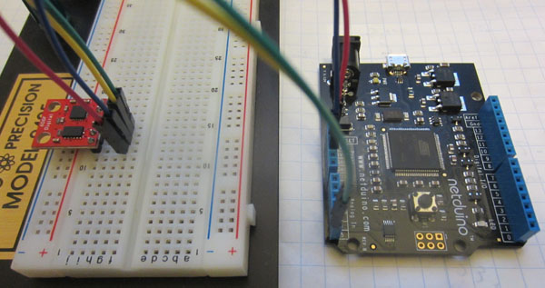
ITG3200 Gyro
Spec SheetGeneral Communication
The gyro is located on the i2c bus at address 0x68. I use the default 100 khz communication rate for i2c bus traffic.
Initialization
There are a few things that need to be initialized before the gyro will start returning data. At the very least, you'll need to write to address 0x16 to turn the gyro on. Refer to the spec sheets for detailed information.
Here's how I'm currently initializing the gyro:- Write 0x09 to address 0x15. This sets the sample rate to 100 hz.
- Write 0x1a to address 0x16. This sets up a 98 hz low pass filter, and more importantly enables the gyro by setting a 2000 degree per second range. If you don't do this, the gyro will not return data!
Reading Data
Data is read from address 0x1d. I'm reading all 6 bytes at the same time for efficiency reasons. For this device, the most significant byte of the 16 bit value is read first, followed by the least significant byte.This makes the data parsing straight forward, and can be accomplished via code similar to:
x = (short)((bufferData[0] << 8) | bufferData[1]);y = (short)((bufferData[2] << 8) | bufferData[3]);
z = (short)((bufferData[4] << 8) | bufferData[5]);
ADXL345 accelerometer
Spec SheetGeneral Communication
The accelerometer is located on the i2c bus at address 0x53. I use the default 100 khz communication rate for i2c bus traffic.
Initialization
Similar to the gyro, the accelerometer needs a bit of initializion before it will start to return values. Refer to the spec sheets for detailed information.
- Write 0x09 to address 0x31. This sets the data format to support a +/- 4g range, and sets the Full_Res bit to use the full resolution.
- Write 0x08 to address 0x2D. This takes the device out of standby mode, and has it start measureing acceleration. This is necessary for the device to return data!
Reading Data
Data is read from address 0x32. I'm reading all 6 bytes at the same time for efficiency reasons. For this device, the least significant byte of the 16 bit value is read first, followed by the most significant byte. Note this is the opposite way that the gyro functionsReading data can be accomplished as such:
x = (short)((bufferData[1] << 8) | bufferData[0]);y = (short)((bufferData[3] << 8) | bufferData[2]);
z = (short)((bufferData[5] << 8) | bufferData[4]);
